How 3D Laser Scanning and Spatial CAD Integration Are Redefining Modern Architecture
 dimensiongauge
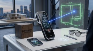
In the evolving landscape of architectural design and structural engineering, accuracy is no longer measured in inches—it is calculated in fractions of a millimeter. The convergence of high-resolution 3D laser scanning, point cloud telemetry, and real-time CAD (Computer-Aided Design) integration has transformed how architects, project managers, and civil engineers approach both retrofits and ground-up builds.
Traditional physical site surveys often lead to costly delays, spatial miscalculations, and unexpected structural collisions during construction. Today, spatial technology bridges the gap between physical reality and digital modeling, enabling seamless workflows through Building Information Modeling (BIM) and Digital Twin simulations.
The Key Evolution: From Manual Surveys to Point Cloud Telemetry
For decades, structural surveys relied on manual measuring tapes, optical transits, and two-dimensional drafting. Modern spatial metrology replaces these prone-to-error methodologies with non-contact Terrestrial Laser Scanners (TLS) and LiDAR-equipped autonomous systems.
What Is Point Cloud Data?
A point cloud is a dense collection of millions of individual 3D coordinates ($X, Y, Z$) captured by laser rangefinders panning across a physical surface. When compiled into CAD or BIM platforms (such as Autodesk Revit or Vectorworks), these data points generate a hyper-realistic digital replica of complex geometries, structural loads, and mechanical clearance paths.
High-Precision Surveying Technologies Compared
| Technology | Spatial Precision | Optimal Range | Primary Architectural Use Case |
| Terrestrial Laser Scanning (TLS) | Sub-millimeter ($\le 1\text{ mm}$) | Up to 350 meters | Structural integrity analysis & historical preservation |
| Mobile LiDAR Mapping | 5mm – 10mm | Continuous capture | Large-scale interior mapping & commercial real estate |
| Photogrammetry (Drone-Based) | 10mm – 20mm | Kilometers | Topographic terrain analysis & roof inspections |
| Handheld Spatial Scanners | Sub-millimeter ($\approx 0.5\text{ mm}$) | Close-range ($1 - 3\text{m}$) | MEP (Mechanical, Electrical, Plumbing) collision detection |
Core Benefits of Spatial CAD Integration in Structural Engineering
1. Zero-Collision Mechanical & Structural Retrofitting
Renovating legacy structures—especially historic urban buildings—presents massive structural risks due to settled foundations and non-standard wall angles. By converting 3D scans directly into BIM geometry, engineers can run automated Clash Detection tests. This identifies pipe conflicts, load-bearing oversights, and ductwork mismatches long before steel beams or pre-fabricated elements arrive on site.
2. Digital Twin Creation for Facility Management
Beyond construction, 3D spatial data forms the foundation of a building's Digital Twin—a dynamic 3D virtual model that continuously updates via IoT sensors. Property managers can measure structural strain, monitor micro-vibrations, and track thermal efficiency with precise spatial context.
3. Streamlined Material Estimation & Reduced Waste
Precision measurement directly impacts bottom-line budgets. Accurate 3D volumetric scans calculate exact concrete pours, structural steel requirements, and glass panel dimensions. This drastically reduces material over-ordering and site waste, aligning project execution with modern sustainability standards.
Step-by-Step Workflow: Scan-to-BIM Implementation
- Spatial Data Acquisition: Deploy Terrestrial Laser Scanners to capture high-density point clouds from multiple station viewpoints.
- Registration & Filtering: Use processing software (e.g., Leica Cyclone or Faro Scene) to stitch disparate scans together and filter out ambient noise.
- CAD/BIM Import: Export unified coordinate data into
.RCPor.E57file formats for direct import into 3D CAD modeling environments. - Parametric Modeling: Convert raw points into parametric elements—walls, columns, MEP systems, and structural slabs.
- Structural Integrity Verification: Conduct finite element analysis (FEA) on the virtual model to test load tolerances under varying environmental stress factors.
Frequently Asked Questions (FAQs)
What is the difference between photogrammetry and 3D laser scanning in architecture?
3D laser scanning uses active laser light (time-of-flight or phase-shift) to measure physical distance directly with millimeter precision. Photogrammetry constructs 3D models by triangulating multiple overlapping high-resolution photographs. While photogrammetry offers rich visual textures, laser scanning provides superior dimensional accuracy for load-bearing structural engineering.
How do point cloud files integrate into software like AutoCAD or Revit?
Point cloud files are indexed into unified spatial formats (such as .RCP or .E57). Once attached inside AutoCAD or Revit, the software locks the point data to exact project coordinates, allowing designers to trace, snap, and model directly over real-world measurements.
Why is Scan-to-BIM essential for historic preservation projects?
Historic structures often lack original blueprints or have undergone structural shifts over time. Scan-to-BIM captures non-standard curves, uneven settling, and intricate architectural detail without physical contact, preserving the building while providing precise schematics for restoration.
Final Thoughts
The modern architectural office is no longer just a drafting studio—it is a spatial data laboratory. Embracing high-precision 3D laser scanning and Scan-to-BIM workflows allows architects and structural engineers to mitigate risk, eliminate site rework, and build with unprecedented dimensional confidence.